
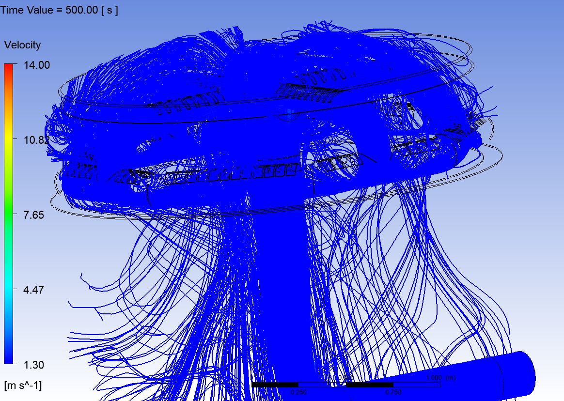
Turbulence Drivers
Geometry, discharge volume and aspect ratio dictate the balance between flow momentum and buoyancy.
CFD-validated buffer tank performance for a data centre with demanding space and PUE constraints.
ΔT retention over a 2-hour discharge
Reduction in flow short-circuiting
Pumping energy saved
Horizontal tanks modelled in the study
Buffer tanks only deliver value when cold and warm water stay separated. In horizontal tanks, poorly designed inlets drive turbulence that mixes the layers, eroding usable capacity and forcing pumps to work harder.
We used computational fluid dynamics to visualise temperature distribution inside the tank, test design alternatives and select the configuration that preserves stratification.
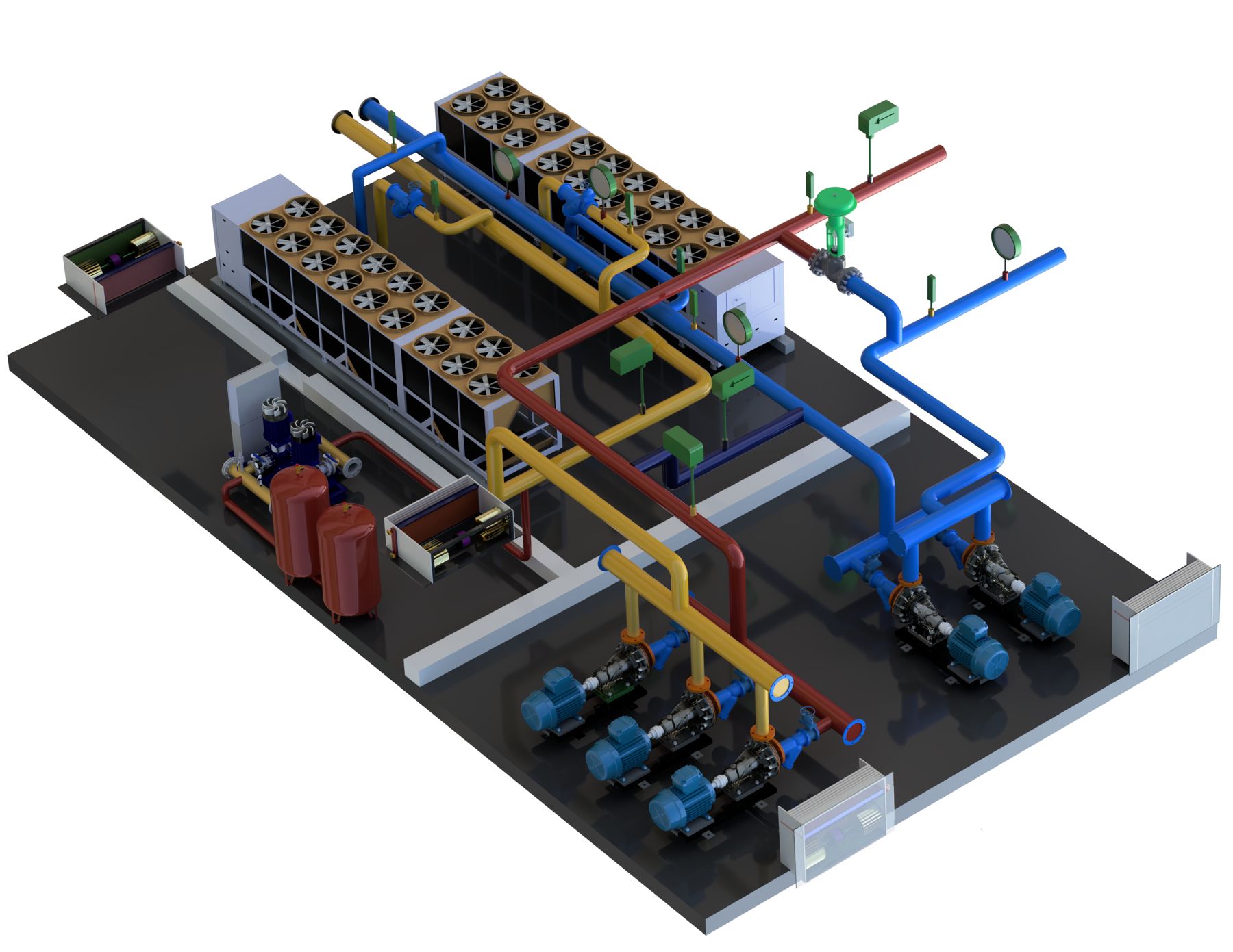
Four factors decided whether the tanks would perform, each tested and refined in simulation before fabrication.
Geometry, discharge volume and aspect ratio dictate the balance between flow momentum and buoyancy.
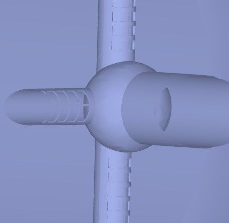
Pipe sizing, inlet orientation and diffuser layout determine how much mixing occurs.
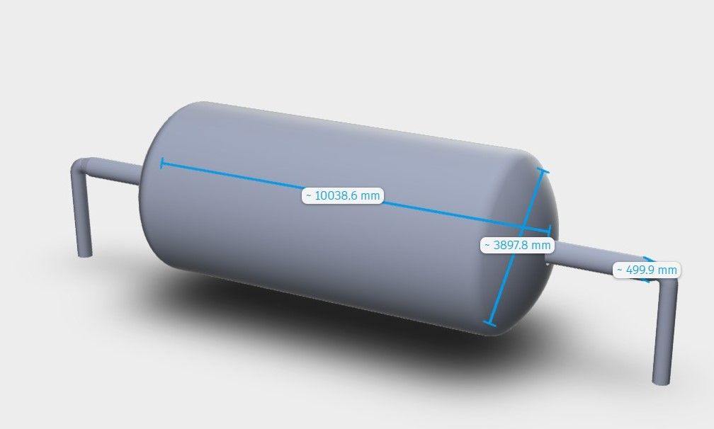
Eighteen horizontal tanks studied under the data centre’s strict space constraints.
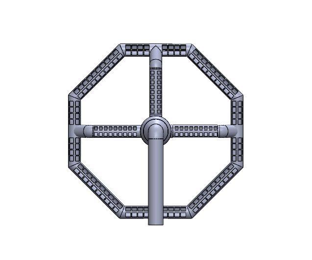
Avoids baffle losses to help the data centre hit its PUE targets.
Capture site constraints, load profiles and performance targets including PUE.
Build CFD models of the tank geometry, inlets and diffusers.
Compare alternatives on stratification, short-circuiting and pressure loss.
Issue a validated design specification ready for fabrication.
Share your plant, network or building challenge. Our team will respond within one business day.